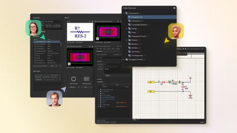


We are happy to announce the release of the new Altium Designer Getting Started User Guide. Whether you are new to Altium Designer or you want to brush up on some topics, the Altium Designer Getting Started User Guide will take you from a beginner to a master in PCB design. This is only the beginning! This guide will be updated with new information based on user feedback. Let’s first go over the contents of the guide.
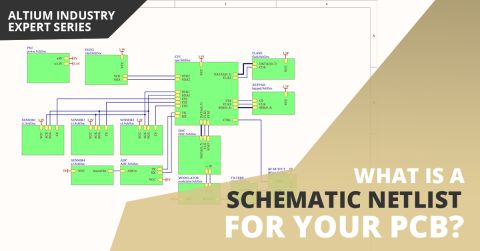
If you’ve created your next great schematic, there is a lot going on behind the scenes in your design software. The connectivity between components in your schematic can be reduced to a small number of logical and electrical identifiers. The schematic may provide a graphical picture showing connections between different components and pins, but to really understand everything about your design, you’ll need an important document. A schematic
Your modern digital board is most likely classified as high speed, regardless of whether you looked at the datasheets for your components. Designing your board successfully will take some important steps when you begin your design. Aside from floorplanning and stackup design, your routing strategy will need to operate within some important PCB design constraints. After you capture your schematic as an initial layout and create an initial
Publishing Destinations offer you the ability to publish release data for a revision of a PCB Fabrication Data Item, PCB Assembly Data Item, or PCB Project Design Item, directly from a Workspace, or Output Job, to a storage space – such as Box.com, Amazon S3, an FTP server, or a simple folder location on a shared network. This enables you to host generated release data securely, while providing…
The design rules of the Manufacturing category are described below. The Manufacturing category of design rules. Minimum Annular Ring Default Rule: not required This rule specifies the minimum annular ring required for a pad or via. The annular ring is measured radially, from the edge of the pad/via hole to the edge of the pad/via (also referred to as the land perimeter). For very dense designs,…
The design rules of the Testpoint category are described below. The Testpoint category of design rules. Fabrication and Assembly Testpoint Style Default Rule: required i The Fabrication Testpoint Style and Assembly Testpoint Style design rules specify the allowable physical parameters of pads and vias that are to be considered for use as testpoints for bare-board fabrication testing, or in…
The design rules of the Plane category are described below. The Plane category of design rules. Power Plane Connect Style Default Rule: required i This rule specifies the style of the connection from a component pin to a power plane. Constraints Default constraints for the Power Plane Connect Style rule. Roll the mouse over the image to compare the two modes of operation available. Mode of…
The design rules of the SMT category are described below. The SMT category of design rules. SMD To Corner Default Rule: not required This rule specifies the minimum distance from the edge of a surface mount pad to the first routing corner. Constraints Default constraints for the SMD To Corner rule Distance - the value for the minimum permissible distance from the SMD pad edge to the start of the…
When UI.ModernDesignReusePanel is in the Public state - update the blue box below with the source code of the 'Open Beta Feature Moves to Public' snippet. The Design Reuse panel that is used to manage reuse blocks and described on this page is in Open Beta and available when the UI.ModernDesignReusePanel option is enabled in the Advanced Settings dialog. When this option is disabled, the previous…
Parent page: Design Panels Reference Workspace panels are essential elements of the Altium Designer environment. Whether specific to a particular document editor, or used on a more global, system-wide level, they present information and controls that aid productivity and allow you to design more efficiently. Accessing Panels When Altium Designer is first started, a number of panels will already…
Altium Designer combines a myriad of features and functionality, including: Advanced routing technology Support for cutting-edge rigid-flex board design Powerful data management tools ECAD Libraries containing over 300,000 ready-to-use components Powerful design reuse tools Real-time cost estimation and tracking Dynamic supply chain intelligence Native 3D visualizations and clearance checking…
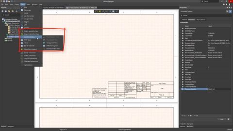
When working with a graphical document, such as a schematic sheet, PCB document, or Draftsman document, you can zoom and pan the document to focus on a specific document area. The basic shortcuts that can be used to do this are: Ctrl+Mouse Wheel to zoom in and out Right-Click, Hold&Drag to slide the document around The View main menu includes a number of commands that can be used to control the…
Supported MCAD Software The following MCAD platforms and versions are currently supported: Autodesk Inventor Professional® Autodesk Fusion® (Microsoft Windows version only. Autodesk Fusion Personal license only supported by Altium CircuitMaker) Dassault Systemes SOLIDWORKS® (Standard, Pro & Premium) PTC Creo Parametric® Siemens® NX™ - (for designers with an Altium Enterprise Solution) Onshape®…
Solutions for Every Role and Team
Discover and evaluate design options earlier
Develop in one shared workspace
Scale with control and compliance
Connect every stage of hardware development
Learn More