



Digital, Analog, and Mixed-Signal I/O Expansion

At a Glance
You can expand your microcontroller's GPIO pin count with some simple ASICs or a custom interface. Mixed-signal processors give an option to expand digital and analog interfaces for unique applications.


At some point, every designer has been in this situation. You're working on your schematics, but your main microcontroller is running out of I/O pins. The apparent obvious solution is to just use a larger microcontroller, but many times for cost or firmware compatibility reasons, that is not always the most useful path forward. Instead, there are other ways to expand GPIO interfaces and analog input interfaces so they can accept a larger number of signals.
Rather than simply using a large microcontroller, designers normally add additional ASICs to the design to expand the number of available I/O pins. While this is usually fine for digital inputs on the microcontroller, it does not scale to mixed signal interface expansion. These interfaces are very important in a variety of sensor applications, many of which require custom logic. However, when you can expand an interface via a serial protocol and a multiplexing strategy, it is possible to implement the strategies with mixed signal systems without an excessive number of ASICs.
Digital I/O Expansion
The most common approach to expanding digital I/O is an I2C or SPI GPIO expander. These are dedicated ICs that present a bank of general-purpose digital pins, typically 8 or 16, controlled entirely through a serial bus. The microcontroller communicates with the expander over I2C or SPI, reading input states or writing output states to registers inside the device. From the firmware perspective, each expander appears as a set of addressable registers, and multiple expanders can share the same bus by assigning unique addresses, usually set with external address pins.
Most I2C GPIO expanders support configuring each pin independently as an input or output. Many also include optional internal pull-up resistors and interrupt outputs, allowing the expander to alert the host microcontroller when an input state changes rather than requiring continuous reading of the interface.
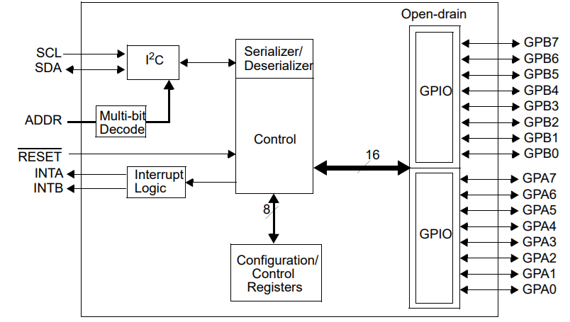
I2C-controlled I/O expander block diagram
When selecting an expander, confirm that the output drive strength meets your load requirements and that the device's supply voltage is compatible with your logic levels without requiring additional translation. Timing is also an important factor in the outputs from an expander: signals requiring deterministic timing in the low-microsecond range should instead consider a dedicated microcontroller pin or a shift register approach.
Analog I/O Expansion
Expansion of an analog interface in a microcontroller is more difficult because there is some ambiguity involved. For example, are we expanding a comparator pin to a larger number of comparator inputs, or are we expanding an ADC input to a larger number of ADC inputs?
One option for doing this is to use a multiplexer or a digitally controlled switch. A multiplexer can be controlled with some GPIOs to be made addressable, which allows a single analog input to be switched between multiple analog signals. By enforcing some sampling time and switching between each signal within the timing window, all of the analog signals can be sampled with a multiplexer.

Analog multiplexer and switch comparison [Source: Digi-Key]
Switches operate in a similar way although they will mimic a standard mechanical switch, i.e., SPDT, DPDT, etc. Therefore, they would be less often used for I/O expansion, although single-pole switch array ICs can effectively function as a multiplexer.
Analog multiplexers have some important specifications that will impact signal quality:
- On-state impedance
- Settling time
- Bandwidth and harmonic distortion
- Leakage current
Multiplexing triggered with logic gates, op-amps, and comparators can have a range of possible specifications, often requiring simulation to ensure the design will meet performance requirements.
Mixed Signal I/O Expansion
What about interfaces that involve sensing digital and analog input simultaneously? How do we expand these?
While you could buy a set of ASICs and start allocating a large number of pins to controlling your I/O expansion, you can expand both digital and analog interfaces simultaneously with a programmable mixed signal processor. These components offer a flexible option for expanding digital and or analog I/O from the same microcontroller.
Programmable mixed signal processors integrate configurable analog blocks alongside digital logic and a communication interface in a single package. The host microcontroller connects to the device over I2C or SPI and configures internal resources through register writes. The configuration is stored in on-chip NVM, so the device powers up with a defined I/O mapping without requiring runtime initialization from the host if the application demands it.
The GreenPAK family from Renesas is a representative example of this architecture. A typical GreenPAK device used for mixed signal I/O expansion provides the following internal resources that can be routed to external pins through a configurable interconnect matrix:
GreenPAK feature | Function |
ADC (8-10 bit) | Samples external analog signals and reports digitized values over I2C |
DAC outputs (e.g., in AnalogPAK devices) | Generates analog reference or threshold voltages for external circuits |
Analog comparators | Provides window detection or threshold crossing alerts without host polling |
Programmable references | Biases internal components in mixed-signal macrocells |
Digital LUTs and DFFs | Implements combinational or sequential logic for local signal conditioning |
Counter/delay blocks | Generates timing, debounce, or PWM signals on digital output pins |
I2C slave interface | Allows the host microcontroller to read analog measurements and configure digital states |
This architecture allows a single device to replace what would otherwise require a separate GPIO expander, an external ADC, and discrete comparator circuitry. These components are very compact and do not offer a high I/O count for every package option. However, in some ways this is desirable as it allows expander footprints to be kept small if needed or easily parallelized with more than one package.
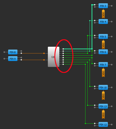
GreenPAK I/O expander design in the Go Configure software.
The developer tools in Renesas GreenPAK give designers the ability to develop fully custom digital, analog, or mixed signal ICs. These programmable mixed-signal processors allow consolidation of functions found in clock and signal management circuitry, allowing for smaller, more efficient systems.
To learn more, take a look at the GreenPAK components and reference examples.
Whether you need to build reliable power electronics or advanced digital systems, use the complete set of PCB design features and world-class CAD tools offered by Altium to implement your GreenPAK solutions. Altium provides the world’s premier electronic product development platform, complete with the industry’s best PCB design tools and cross-disciplinary collaboration features for advanced design teams. Contact an expert at Altium today!

About Author
Related Resources
Related Technical Documentation
Table of Contents
Solutions for Every Role and Team
- Discover and evaluate design options earlier
- Develop in one shared workspace
- Scale with control and compliance
- Connect every stage of hardware development
Learn More
Thank you, you are now subscribed to updates.



