



Practical Design Insights for Flexible Circuit Stiffeners

At a Glance
Learn how flexible circuit stiffeners support heavy components and control bends. Compare FR4 vs. polyimide, adhesives, and coverlay overlap before fabrication.


Flexible circuits offer remarkable versatility, allowing engineers to create designs that can bend, fold, and conform to various shapes, solving many space and packaging challenges. However, their flexibility can introduce structural weaknesses or wear-and-tear concerns in certain areas. To overcome these issues, stiffeners are often used as a targeted solution.
Stiffeners, typically made from FR4 or polyimide, provide localized support where extra rigidity is needed, without compromising the overall flexibility of the design. Here’s a breakdown of how to effectively integrate stiffeners into your flexible circuit design to maximize performance and durability.
Key Takeaways
- Stiffeners add targeted reinforcement in flex circuits without turning the entire assembly into a rigid structure.
- FR4 is commonly chosen for connector and component support, while polyimide is useful for thickness control, abrasion protection, and bend management.
- Adhesive selection affects strength, cost, processing time, and long-term reliability.
- Coverlay overlap, edge placement, and stiffness transitions should be reviewed early with the fabricator.
- A simple material comparison and workflow check can prevent late redesigns during fabrication or assembly.
Supporting Heavy Components with FR4 Stiffeners
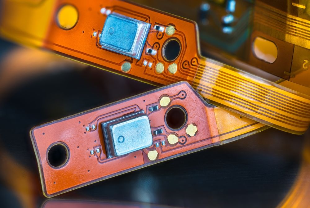
If your flexible circuit includes heavy connectors or components, FR4 stiffeners are your go-to solution. FR4, the material commonly used in rigid PCBs, can be added to key areas of the flexible circuit to provide the necessary mechanical support. This helps prevent damage to the copper traces and reduces the risk of solder joints failing due to excessive movement.
- Connector Areas: For connectors that are heavy relative to the circuit, adding an FR4 stiffener underneath can prevent bending and stress that could otherwise damage the circuit.
- Component Stability: If there are numerous small components, or components subject to vibration or mechanical stress, an FR4 stiffener provides a sturdy backing, ensuring the area remains rigid and protected.
Design Tip: Be careful not to confuse a flexible circuit with an FR4 stiffener for a rigid-flex design. The stiffener serves a mechanical purpose only, with no electrical connections, unlike rigid-flex constructions which integrate electrical pathways between rigid and flexible layers.
Adhesive Options: FR4 stiffeners can be attached using either pressure-sensitive adhesives (PSA) or thermal-set adhesives. PSA is generally more cost-effective for low-demand environments, while thermal-set adhesives offer better strength for harsher conditions but come with added cost due to extra processing.
Polyimide Stiffeners
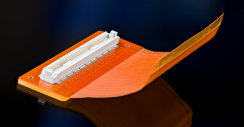
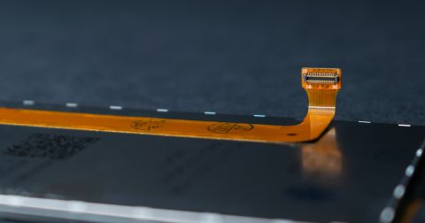
For connector interfaces that require precise thickness, such as ZIF (Zero Insertion Force) connectors, polyimide stiffeners provide the needed build-up. Flexible circuits often need to meet specific thickness tolerances at connection points to ensure a reliable electrical contact. Adding a polyimide layer in these areas brings the circuit to the required thickness without adding bulk to the rest of the design.
- Insertion Connectors: When working with insertion connectors, polyimide stiffeners help meet the exact thickness specs, ensuring proper insertion and electrical connection.
- Wear Protection: In areas where the circuit may experience friction or wear during its lifecycle, adding a polyimide stiffener can prevent damage. The polyimide takes the brunt of the wear, safeguarding the underlying circuitry.
Design Tip: Always ensure the stiffener and coverlay overlap by at least 0.030 inches to avoid creating stress points that could lead to mechanical failure over time.
Controlling Bend Locations with Polyimide Stiffeners
One of the unique advantages of polyimide stiffeners is their ability to control where the circuit bends. In some designs, certain areas of the flexible circuit might naturally bend in ways that could interfere with other components or connectors. By adding polyimide stiffeners in strategic locations, you can direct the flexing to occur in more desirable areas.
Applications for Controlled Bending
- Bend Guidance: Placing polyimide stiffeners around a bend zone ensures the circuit flexes exactly where it’s designed to, protecting sensitive areas from undue stress.
- Installation Clarity: For assembly operators, polyimide stiffeners act as a clear visual and functional guide, indicating the correct areas for bending and flexing.
Adhesive Options: Unlike FR4, polyimide stiffeners are often laminated during the same process step as the coverlay, streamlining the production process. This can save time and cost, particularly when using thermal-set adhesives. However, if pressure-sensitive adhesive is specified, it might introduce extra steps, leading to higher costs.
Reducing Stress on Solder Joints with Stiffeners
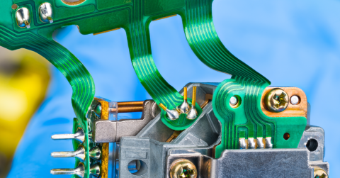
Flexible circuits can be particularly vulnerable at the solder joints, especially in areas with frequent movement. Stiffeners can reduce this stress by preventing excessive bending near these sensitive joints. Both FR4 and polyimide stiffeners help in this regard, depending on the weight and positioning of the components.
Practical Tip: Use FR4 for heavier components that need rigid support and polyimide for lighter components where flexibility needs to be preserved, but some additional rigidity is required to protect the soldered connections.
Cost-Effective Design Strategies
Keeping costs down while ensuring high performance is often a balancing act. Here are a few strategies to consider:
- Standardize Stiffener Thickness: Maintaining uniform thickness for all stiffeners in a design reduces processing time during fabrication and can help lower costs.
- Choose Adhesives Wisely: For low-cost designs where the environment is not demanding, opting for pressure-sensitive adhesive over thermal-set adhesive can offer savings.
- Lamination Efficiency: Take advantage of the fact that polyimide stiffeners can be laminated along with the coverlay, avoiding additional processing steps and reducing overall costs.
Incorporating stiffeners into flexible circuit designs provides a practical way to tackle common challenges, from supporting heavy components to controlling bend locations and reducing stress on solder joints. By carefully selecting the right type of stiffener (FR4 for rigid support or polyimide for versatility) you can enhance the durability and functionality of your design without compromising flexibility.
Designing flex or rigid-flex boards solo or in a small team? Altium Develop gives you Altium-grade design tools, including rigid-flex layer stack management and 3D checking. You can also share the design with your fabricator and keep comments tied to the right version, only when it helps. Learn more →
Frequently Asked Questions
When Should a Flex Circuit Use an FR4 Stiffener?
Use FR4 when a mounted connector, large component, or mechanically loaded area needs a firm backing. The goal is to reduce local movement while leaving nearby flex regions able to bend.
When Is Polyimide Better Than FR4?
Polyimide is useful when the design needs thickness control, abrasion resistance, or guided flexing without the bulk of a rigid backing. It is especially common near insertion tails and bend-management features.
How Much Overlap Should There Be Between Coverlay and Stiffener?
A common design rule is to maintain at least 0.030 inches of overlap so the transition does not create a sharp stress riser. Designers should still confirm the value with the fabricator because adhesive, copper weight, and bend radius can change the preferred construction.
Are Stiffeners the Same as Rigid-Flex Layers?
No. A stiffener is a mechanical reinforcement, while a rigid-flex section includes electrically functional rigid layers tied into the circuit stackup.

About Author
Related Resources
Related Technical Documentation
Table of Contents
Design to Release, Without the Friction
- Keep reviews tied to the right version
- Reduce handoff confusion and rework
- Spot sourcing and release risk earlier
- Work solo, share when needed
Get Started
Thank you, you are now subscribed to updates.