

.
In all of our classes and consulting activities as well as the numerous articles we create, we always stress the importance of PCB documentation. Along with the PCB Fabrication Specification, this documentation is crucial to ensuring that a PCB is built right the first time and every time thereafter. Because the creation of this documentation occurs later during the design process, this step is given short shrift and/or not enough attention. When
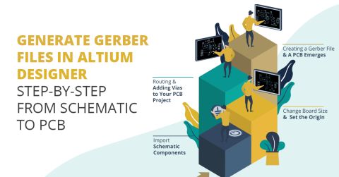
Looking for the best approach for CAM jobs? Learn how to make PCB Gerber files in Altium Designer from your circuit board layout. Altium's CAM tools can help you quickly create PCB Gerber files.
Learn everything you need to know to have you board successfully assembled, including assembly drawing requirements, adding notes, and cautionary markings.
Every electronic product and PCB assembly needs a bill of materials, or BOM. Here's what is in the BOM and how to keep it organized.
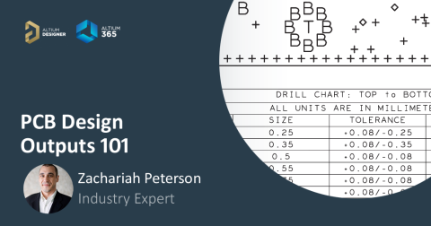
Make sure you know which PCB design output files your fabricator and assembler need to ensure they can build your PCBA.
Learn about the important PCB assembly output files. Manufacturers use these to source components, understand process requirements, and assemble the PCBA.
Manage each variant of your PCB design in a single platform, without complicated sheets, folder structures, or multiple PLM entries.
Contained in your PCB manufacturing data is the golden goose that drives your profitability. Make sure you keep track of who gets your data and what's kept secret.
Sometimes you might take a product or a prototype in-house to assemble. Here's how to prepare for hand PCB assembly.
A finished PCBA that will be deployed in the field should pass several tests to ensure reliability and stable operation. Industry standards specify multiple testing methodologies, performance requirements, evaluation metrics, even test fixtures that must be used to assess electrical behavior, thermal cycling resistance, long-term thermal stability, ability to withstand thermal shock, and much more. With Altium Designer, you’ll have a complete
The Altium 365 Workspace project view provides design data comparison features that allow you to compare data changes that have occurred between different project releases and/or commits. Particularly valuable for performing final checks prior to sending your product data to the manufacturing side, the features allow you to determine exactly what changes have occurred in your Gerber (or ODB++),…
The standalone Altium 365 Gerber Comparison viewer provides free access to graphically view the differences between Gerber fabrication files through your web browser. This offers a quick and easy solution for checking a design's fabrication output between release iterations or prior to sending your board production data out to manufacture. As a free service developed and provided by Altium, the…
When BOM.CoDesign is in the Released state - update the blue box below with the source code of the 'Public Feature Moves to Released' snippet. The BOM CoDesign functionality is available when the BOM.CoDesign option is enabled in the Advanced Settings dialog. The BOM CoDesign functionality facilitates collaborative BOM design between the ECAD and Procurement domains. This functionality enables…
When a product needs to be designed and produced as a number of variations of that product, say where each has different options or capabilities, the ability to implement Design Variants avoids the need to create a unique version of the design for each variation. In practice, a Design Variant uses the same base design, but the PCB assembly is loaded with the set of components specified by the…
A large variety of outputs can be generated for and from a PCB design, and each output type has its own settings. The best way to manage this multitude of outputs in Altium Designer is to use an Output Job file, or 'OutJob' as it is more commonly known. An OutJob is simply a pre-configured set of outputs. Each output is configured with its own settings and its own output format, for example…
The final phase of the board design cycle is to generate the output files needed to fabricate, assemble and test the printed circuit board. To do this, you need to generate a variety of output files, in a variety of formats. The ultimate objective is to fabricate and assemble the board. As the designer you have the choice of individually configuring and generating the outputs via the schematic…
Print-based output for your PCB project in Altium Designer is available through creating a output job configuration file (*.OutJob). When you create a job output there is a range of manufacturing documentation available for output including common two-dimensional PCB printouts, such as a composite drawings and schematic drawings. 2D print output is configured in the PCB Printout Properties dialog…
Parent page: More about Outputs In Altium Designer, the ability to take a snapshot of your PCB as a 3D printout provides a quick and easy way to share the look of the finished product with others, prior to physical production of the board. However, there's always something lacking when it comes to a single 3D print. You inevitably want to tilt the board, rotate it, or flip it between component…
Altium Designer users have long enjoyed the ability to interactively view PCB designs in fully rendered 3D, which provides a unique insight into the real structure of the board design, its components and associated mechanical parts. There are significant advantages in being able to bring this 3D capability to those outside the immediate design team, such as fabrication and assembly houses, and…
PCB layers are created from photographic film that has been exposed to light. Apertures are the physical openings through which the light shines on the film. CAM data includes aperture definitions (size and shape), plus instructions about where to flash the light through apertures, and where to draw lines on the film by moving between locations with the light beam still on. Different pad sizes…
Solutions for Every Role and Team
Discover and evaluate design options earlier
Develop in one shared workspace
Scale with control and compliance
Connect every stage of hardware development
Learn More