


Eliminating Audio Ground Loops: Designing a USB Type-C Isolator with Advanced Power Filtering

Ground loops in audio systems can be a persistent annoyance, especially when they involve a mixture of both digital and audio interfaces. These issues often present themselves in my office as an irritating buzzing noise, mainly when my computer is under heavy GPU loads. To tackle this, let's embark on a journey to design an effective solution - a USB isolator enhanced with USB Type-C connectors and advanced power filtering!Ground loops in audio systems can be a persistent annoyance, especially when they involve a mixture of both digital and audio interfaces. These issues often present themselves in my office as an irritating buzzing noise, mainly when my computer is under heavy GPU loads. To tackle this, let's embark on a journey to design an effective solution - a USB isolator enhanced with USB Type-C connectors and advanced power filtering!

A 3D render of the finished USB 2.0 High-Speed Isolator is shown above.
What Are Ground Loops?
When connecting an audio device to your computer or inadvertently touching the tip of an audio cable connected to an audio amplifier, it's common to hear a 50 Hz or 60 Hz hum emanating from the speaker. But that's not the only frequency that can make it to the speakers.
Different boards in a project, or even different parts of the same PCB, can have "ground" references at different electrical potentials. Whenever there is a potential difference across a conductor, current will flow to attempt to equalize the imbalance.
In the case of the audio amplifier, the audible hum is most often synchronized with the mains-voltage frequency. It happens because the idealized "ground" reference we use when designing electrical and electronic circuits is far from ideal in real life. The alternating current, through cross-talk, ground plane disturbances, or antenna effects, can induce a tiny ripple in the ground reference in one part of the board, and that ripple spreads outwards across your ground reference like waves in a pond. The fluctuation creates a potential difference between your board and any other boards that are connected to it. Eventually, the disturbance makes it to an audio amplifier and then to your speaker.
The best way to eliminate the hum is to not introduce it into the circuit in the first place by carefully designing continuous return paths for all signal and power lines and paying attention to best practices in signal integrity and power integrity design. However, when dealing with circuit boards others have made that are outside of your control, you don't always have that option. That leaves a second best way to eliminate the hum: electrically separate the two ground references so that no current can move from one "ground" reference to another.
Conceptualizing the Solution
A USB isolator breaks ground loops by electrically isolating the audio interface from the computer, thereby cutting off the noise path. Our design incorporates the latest USB technology - the versatile USB Type-C connector - and power filtering on the power lines. Unfortunately, there aren't any good options for USB-3.0 isolation ICs on the market just yet, so I'll be using a USB-2.0 IC for the task.

The schematic for this project includes the USB Isolator IC (center), two USB-C connectors (left and right), two DC-DC converters (top), and a variety of support components.
Design Process
Central to our design is the Analog Devices ADUM4165, chosen for its ability to isolate USB data lines effectively.

The ADUM4165 functional block diagram. The upstream device and power connect to pins 1-10 on the left side, and the downstream device and power connect to pins 11-20 on the right side of the device.
This IC forms the backbone of our isolator, ensuring clean data transmission. I will add an isolated power supply and place it into the Hammond Manufacturing 1455D602 extruded aluminum enclosure. I will use Altium Co-design and 3D modeling to ensure it will fit.
USB-C
Implementing USB 2.0 over a USB-3.0 Type-C connector might seem daunting due to the high pin count and complex configurations. However, it's more straightforward than it appears. And if you're very overwhelmed by the pin-count, reduced-pin-count USB-2.0 Type-C connectors are available for purchase.
The key to success lies in understanding the role of Configuration Channel (CC) pins and their role in determining cable orientation and connection type. Resistors connected to the CC pins on the upstream and downstream ports form a two-resistor divider with the center-tap voltage at the CC pin, indicating the current requirements and capabilities of the downstream device.

Image from page 154 of the USB Type-C Spec R2.3-October 2023.pdf
In our design, I'll add 5.1 kΩ pull-down resistors to the upstream connector pins CC1 and CC2 (A5 and B5) and 22 kΩ pull-up resistors to the downstream connector pins CC1 and CC2. In a USB-C connector, these lines are D+ (A6 and B6) and D- (A7 and B7). You must short the respective A and B pins (e.g., A6 to B6, A7 to B7) to ensure connectivity regardless of the plug's orientation.

While the connectors have a large number of pins, only a few need to be connected to have a successfully implemented USB 2.0 Type-C connector.
Power and Ground Connections: I'll also need to connect the VBUS (power) and GND (ground) pins along with the data lines.
Power Supply Considerations
Power quality is paramount in audio equipment. To this end, I've selected the Gaptec 3S7B-0509S3U 5V to 9V module for its high efficiency, isolation, and low noise profile compared to similar components I have tested from other manufacturers. This model is a semi-regulated supply module that requires minimal support circuitry. Its output voltage varies with load, prompting our choice of a 3W 9V output. The isolator's output feeds into a tightly regulated 5V non-isolated module, also from Gaptec, which my testing has shown has high efficiency and minimal noise.
Despite the low noise of the 5V module, its nature as a switching supply introduces some level of switching noise. To combat this, I've incorporated a Pi filter in the output stage, aggressively targeting the 400kHz switching frequency of the modules.

The power supply section of the schematic is shown above.
Assembly and Testing
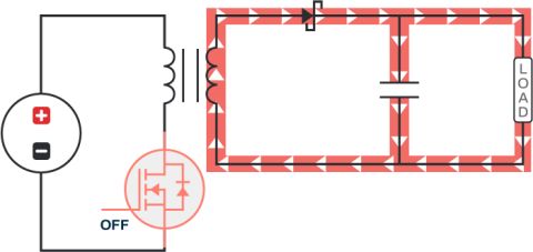
With the design finalized, the next phase involves assembling and testing the board. Tools like the Omicron Lab Bode 100 Vector Network Analyser and the Rohde & Schwarz MXO44 oscilloscope are indispensable for testing the power delivery network and filter efficacy. To measure the output ripple most effectively, I soldered BNC connectors directly to a board that only had the filter populated. I also added SMA connectors to another fully populated board with short lengths of coaxial cable. These boards will allow me to test the power filter's performance with the Bode 100, and the overall system with the oscilloscope.

To test the inductor pi-filter on the Bode 100, I'm using the series-through measurement setup. I'm injecting a signal before the filter and measuring the output after the filter.

Frequency Response Analysis: Bode Plot of a PSU Output Filter - Tracing Impedance Over Frequency Range from 100 Hz to 1 MHz.
The graph above demonstrates the decidedly non-linear response of the inductor pi-filter to a range of frequencies. But what does it physically do to the 400 kHz noise (and any other noise) from the switch-mode power supply? For that, we'll switch to the MXO44 and look at the time-domain response of the pre-filtered and filtered 5V regulator output.

The pre-filtered output shows a three mVpp spike at 400 kHz intervals from the switching supply. While that is quite good for a switcher on a 5V rail, we will still pass the output through a pi-filter to remove as much of that as possible.

After the inductor pi-filter, the residual switching noise is indistinguishable from the oscilloscope's noise floor. And if you can't measure it, it might as well not exist.
Conclusion
The project's success in resolving the ground loop issue is a testament to the power of thoughtful design and meticulous testing. It showcases how advanced USB technology and power filtering can coalesce into an effective solution for a common audio problem.
The files are available on GitHub for those interested in exploring further or even replicating this design. Additionally, check out the on-demand webinar where I demonstrate how to use Altium Co-design to integrate my board into an extruded aluminum housing. I demonstrate how to fit the board, make custom end plates, and answer many viewer questions.
The Altium Webinar space is a valuable resource; check it out here!
关于作者
相关资源
相关的技术文档
目录
Take advantage of the world's
most trusted PCB design system.
One interface. One data
model. Endless possibilities.
Effortlessly collaborate with
mechanical designers.
The world's most trusted
PCB design platform
Best in class interactive
routing
View License Options
Thank you, you are now subscribed to updates.


 沪公网安备 31010502006411号