


Serial Communications Protocols: Part Seven - 1-Wire


Many Serial Communication Protocols are available for transferring data between electronic devices, whether that’s a microcontroller reading data from a sensor or sending data to a storage device. This is one of a series of articles that will cover some of the more popular protocols in common usage. We’ll complete the series with a comparison of the advantages and disadvantages of each.
My aim is that the series will prove to be a useful reference next time you find yourself looking to implement a serial communication bus, so you can choose the best option for your particular application.
In this article, we will be looking at the popular 1-Wire protocol.
1-Wire protocol
1-Wire is a low-speed communication bus developed by Dallas Semiconductor Corp. (now Maxim Integrated) that uses one signal data line excluding the ground. It is a master-slave communication system where a master or host device is connected through a single data line to one or more slave devices. Each 1-Wire slave device will have a unique factory-programmed 64-bit identification number (ID), which is that device’s address.
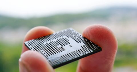
1-Wire devices are usually produced only by Maxim Integrated and are available in various package types, such as the typical transistor TO-92, as well as different integrated circuits. A very popular 1-Wire communicating device is the iButton (also known as a Dallas Key). The iButton is a small modular device used for applications such as data loggers, temperature and humidity sensors, LEDs, Memory devices, adapters, etc. While the iButton has historically been a very popular implementation of 1-Wire, today there are many sensors available from Maxim Integrated which implement the 1-Wire protocol.
In principle, an iButton is a microchip very similar to those used in smart cards. The difference is the microchip is housed in a round stainless steel button and is designed for use in harsh and demanding environments. They rely on physical contacts for connection with the 1-Wire bus.
The typical 1-Wire voltage ranges over which the device operates include:
- 1.71 V (min) to 1.89 V (max)
- 1.71 V (min) to 3.63 V (max)
- 2.97 V (min) to 6.63 V (max)
- 2.8 V (min) to 5.25 V (max)
One of the most interesting features of the 1-Wire bus is that power can be applied over the communications line, rather than needing external power. This can allow external sensors, such as temperature sensors to be connected with just data and ground wires, with the sensor being powered through parasitic power from the data bus. This can save considerable complexity and wiring compared to the other series communications protocols we have investigated in this series.
A typical 1-Wire bus device connection can be seen in the following circuit diagram:

In the above example, one master device is controlling several slave devices.
Most 1-Wire devices require extremely low power and do not require power supply pins. These devices extract the energy they need to operate from the 1-Wire data line, known as a parasitic power supply.

A typical 1-Wire device parasitic power configuration can be seen in the following circuit diagram:

There are various 1-Wire devices, which can be used for applications including temperature sensing, identification, time logging, EEPROM or EPROM (one time programmable), secure authentication, etc. allowing the creation of devices with applications varying from identification, authentication of consumables, PCB and computer accessories, IP protection, control access to the guard tour systems, electronic cash, time and attendance, temperature monitoring of food, or pharmaceutical safety.
The value for the pull-up resistor needed for the 1-Wire connection should be low enough to provide enough current to power the device but not too low such that the slave devices would be unable to successfully pull the data line down to logic level 0.
The typical pull-up resistor values for a 1-Wire connection are between 1 kΩ and 4.7 kΩ. This sets the current from a 5 V power supply between 5 mA and 1.06 mA. As an example, the DS2480B device requires a current value between 1.5 mA and 5 mA to operate, typically 3 mA.
On the 1-Wire bus, there is always one master in overall charge, which may be a personal computer or a microcontroller. The master always initiates activity on the bus to avoid any transmission collisions. The master device is responsible for detecting and managing any collisions from the simultaneous transmission by multiple slave devices.
The devices transmit by using short and long low pulses to represent the data. A 1–15 µs low pulse equates to a logic level 1, while a 60 µs low pulse equates to a logic level 0. The falling (negative) edge of the pulse is used by the slave devices to listen for pulse width. They measure its duration using a very basic monostable multivibrator. The master initiates communications by sending a reset pulse followed by an 8-bit command, and then data is sent or received in groups of 8 bits. Error detection is implemented using a simple 8-bit cyclic redundancy check (CRC).
Summary
This article has looked at some features of the popular 1-Wire protocol and discussed some of its advantages and implementation details. In the other articles in this series, we will look at some of the alternate serial communication protocols available.
Would you like to find out more about how Altium Designer® can help you with your next PCB design? Talk to an expert at Altium.
关于作者
相关资源
从设计到发布,全程无阻碍
- 让评审始终关联到正确的版本
- 减少交接中的混乱和返工
- 更早发现采购与发布风险
- 可独立工作,按需共享
开始使用
Thank you, you are now subscribed to updates.


 沪公网安备 31010502006411号