Common Causes of PCB Short Circuits

At a Glance
PCB short circuits have many possible causes related to common assembly defects and contamination. Learn more in this article.


Short circuits are not a common defect, but the presence of a short circuit can ruin a portion of a device or cause a total failure. Short circuits arise when conductors are bridged, resulting in intermittent problems or permanent failure. They can arise in a PCB during fabrication due to design errors, or they can occur after a product has been placed into the field for a significant period of time.
If you locate a short circuit in your design, it’s important to know what may have caused the short circuit so that the problem can be prevented. This article looks at some of the common causes of shorts in a design and what can be done to prevent them.
What Might Cause Short Circuits in a PCB
External Contamination
External contamination is a common cause of short circuits after long-term operation in a board’s intended environment. It’s also possible for a board to be exposed to substances during assembly that later lead to failure due to a short circuit. These causes of short circuits include:
- Poor cleaning, including of flux residues
- Accumulation of salts after exposure to water
- Exposure to conductive dusts or metal shavings
- Copper dendrite growth between closely-packed conductors
Even if a PCB is placed in a waterproof enclosure and is protected from moisture/debris, the design can still experience a short circuit from flux residues. No-clean flux residues are slightly conductive and can become more conductive, so PCBs assembled with no-clean flux should still be cleaned as a matter of reliability.

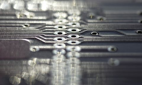
Internal CAF Growth
Contaminants don’t generally infiltrate the interior of the PCB after the board is built, but electrochemical reactions in the internal layers can still lead to short circuits. When metallic or conductive salts are present in the layers of PCB, electrochemical reactions can lead to filament formation between fiberglass bundles in the PCB laminate. This growth is known as conductive anodic filamentation (CAF), and it is known to be an important reliability problem in higher voltage boards. These filaments could bridge two conductors in the internal layers, leading to a short circuit.
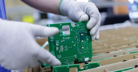
Dirty/Large Solder Paste Stencils and Misalignment
When a PCB is manufactured, solder paste is applied onto component pads and holes before the design is placed into a wave/reflow soldering line. In the process, the solder paste melts and forms the electrical connection from the components to the PCB. If there is a shift in the solder paste application with respect to a component lead, there may be a short circuit between two leads on a component. Leads may connect neighboring pads, or solder could create a bridge between two leads.
The stencil used to apply the solder paste might also have aperture sizes that are mismatched to the size of the PCB pad. If they are too big, solder paste and the resulting joints may be spread over multiple pads. Too small, and the solder joints won’t always reach the lead and form a strong connection. It’s also possible that the pad size in the footprint might be mismatched to the component leads.

High Density
Before any scenarios in which errors, bridges, or shorts occur exist, the foremost demand on component spacing is from operational requirements. There are formalized specifications for spacing: the most commonly cited is IPC-D-279, Section 3.3.9, but there are also manufacturer recommendations, like the chart show below from OCM (units are in mils). Once you have varied component and packaging types and you are working at high density, the specifications often aren’t extensive enough to provide the necessary guidelines.

Example component spacing matrix from OCM. These values are not universal, only recommended, to ensure prevention of solder shorts between components due to solder defects. Link to original page from OCM.
Pick and place machine accuracy also limits the density you can use in your PCB design. If the accuracy of the machine is very high, you’ll have more flexibility to pack in your components. However, also consider the tooling used on the pick and place. Placement tools can extend beyond the edge of the component, which can add difficulty to tightly-packed or small component placing.
The Worst Case: Uncaught Design Errors
Sometimes, a design will simply contain a short circuit that was the result of a design error. If you don’t do a thorough PCB design review before production, the finished PCBAs will contain the short circuit and will not function correctly.
When a short circuit exists in the PCB between two differently-named nets, this error can be spotted in Gerber files during an engineering review with a CAM application. The CAM department at your fabrication house will generally send the project back to you for comments or to correct the errors. Unfortunately, if you are placing your board into a cheap fabrication facility overseas, they probably won’t review your board for netlist mismatch errors. This means your board could get produced with a short circuit.

The typical netlist format used to perform this test is a Wirelist, or IPC-D-356A netlist format. Make sure to include this with your deliverable package when preparing your production order.
If your CAD software is configured to locate shorts in the online DRC system, you’ll catch these errors as soon as they occur and you’ll be able to correct them. The online DRC engine in Altium Designer includes a short circuit setting by default, so you will always be able to catch shorts in the design data during layout and during a final design rule check.
An online DRC engine is one of the most important tools you can use to prevent unintentional short circuits, so make sure you design your PCB with the world’s best CAD tools in Altium Designer®. To implement collaboration in today’s cross-disciplinary environment, innovative companies are using the Altium 365™ platform to easily share design data and put projects into manufacturing.
We have only scratched the surface of what’s possible with Altium Designer on Altium 365. Start your free trial of Altium Designer + Altium 365 today.

关于作者
Related Technical Documentation

相关资源


Thank you, you are now subscribed to updates.


 沪公网安备 31010502006411号