
下载PDF
根据您与 Altium 的关系,您可以通过 Altium Designer 或平台的浏览器界面体验 Altium 平台提供的服务。本页将介绍后者,并概述当您注册 Altium 帐户并登录Altium Platform Interface 时将看到的内容。 有关 Altium 365 平台安全性、可靠性、隐私和合规性的最新信息,请访问Altium 365 信任中心。 对于需要符合美国政府安全法规(如 ITAR 和 EAR)的组织,Altium 提供了基于美国的Altium 365 GovCloud ,在AWS GovCloud区域运行,并提供额外的数据保护措施。 ►更多信息,请参见Altium 365 GovCloud及其相关常见问题解答。 注册Altium账户 访问Altium软件和服务需要您有一个与您的电子邮件地址相关联的Altium Account 。如果您的公司还没有创建一个账户…
Requirements Portal 正在持续开发中。此页面概述了应用在关键更新中新增的功能与改进。 更新 - 2026 年 2 月 2 日 在此版本中,创建与导入需求的流程已更新。要执行任一操作,请进入 Requirements Module,点击 按钮,然后在出现的菜单中选择 Create Requirement 或 Import Requirements。 更多信息请参阅 Creating Requirements 和 Import Requirements 页面。 更新 - 2026 年 1 月 22 日 [collapse collapsed class="" title="Key Highlights" id="key_highlights_update_22_january_2026" data-inclusion-in-toc=""]此版本包含错误修复…
MCAD CoDesigner 如何支持线束设计 MCAD CoDesigner 的线束支持功能会集成线束的 ECAD 与 MCAD 模型。目标是允许 harness geometry 在 MCAD 中完成设计,然后将线束元素的物理参数(长度)回传到 ECAD。 ECAD 与 MCAD 环境之间的共同(且本质上相似)要素在于:线束的原理图/接线图在双方的线束模型交换中基本一致。然而,ECAD 与 MCAD 的物理模型不同:在 ECAD 侧并不存在精确的线束物理模型;而在 MCAD 侧,物理模型由 MCAD CoDesigner 基于 ECAD 侧提供的数据(连接器模型、线束拓扑以及线束对象参数)创建(生成)。 在 ECAD 侧,线束模型的数据来源是线束工程中的布局图。该图是平面的,并非真实线束比例,但包含拓扑以及线束的内部原理图,用于在 MCAD 侧构建线束物理模型草案。 MCAD…
Accessing the ECAD-MCAD Harness Synchronization Capabilities 请注意,本页面中描述的并非所有功能都适用于 Altium MCAD CoDesigner 的所有安装版本。更多信息请参阅右侧的 Feature Availability 面板。 线束同步目前适用于 PTC Creo(MCAD CoDesigner 3.5 及更高版本)和 SOLIDWORKS(MCAD CoDesigner 3.6 及更高版本);对其他 MCAD 的支持将在后续更新中加入。 在 SOLIDWORKS 中,你需要 SOLIDWORKS Routing Electrical(包含在 SOLIDWORKS Premium 套件中)才能同步线束。请注意,SOLIDWORKS Routing Electrical 需要安装 Microsoft Excel…
适用于 Siemens® NX™ 的 Altium CoDesigner 仅面向拥有 Altium Enterprise Solution 的设计人员提供。 适用于 Siemens NX 的 Altium CoDesigner 已在 Altium CoDesigner 3.0 中结束 Beta 阶段。 Altium CoDesigner 是一个用于在 ECAD 与 MCAD 设计领域之间传输印制电路板设计的接口。一旦将 CoDesigner 插件添加到你的 MCAD 软件中,CoDesigner 就可以在两端来回传递设计变更。设计变更通过 Altium Workspace 进行传递,Workspace 充当 ECAD 与 MCAD 领域之间的桥梁。 ► 检查你的 MCAD 软件与 CoDesigner 之间的版本兼容性 要在 Siemens NX 中访问 Altium…
父页面: 安装与配置 Altium CoDesigner Altium CoDesigner 是一个用于在 ECAD 和 MCAD 设计领域之间传输印刷电路板设计的接口。一旦 CoDesigner 插件被添加到您的 MCAD 软件中,CoDesigner 就可以来回传递设计更改。设计更改通过 Altium 工作区传递,该工作区充当 ECAD 和 MCAD 领域之间的桥梁。 ► 检查您的 MCAD 软件与 CoDesigner 之间的版本兼容性 要在 SOLIDWORKS® 中访问 Altium CoDesigner 面板,您必须安装一个插件(插件),具体步骤如下。您可以从 Altium 网站下载页面下载 MCAD CoDesigner 插件。 在 SOLIDWORKS 中安装和配置 CoDesigner 要在 SOLIDWORKS® 中进行接口操作,您需要安装 Altium…
Altium CoDesigner 是一个用于在 ECAD 与 MCAD 设计领域之间传递印制电路板(PCB)设计的接口。将 CoDesigner 插件添加到你的 MCAD 软件后,CoDesigner 就可以在 MCAD 软件与 Altium ECAD 软件之间双向传递设计变更。设计变更通过 Altium Workspace 进行传递,Workspace 充当 ECAD 与 MCAD 领域之间的桥梁。 ► 检查你的 MCAD 软件与 CoDesigner 之间的版本兼容性 要在 PTC Creo® Parametric™ 中访问 Altium CoDesigner 面板,你必须安装一个附加组件(Add-In/Plugin),如下所述。你可以从 Altium 网站下载页面下载 MCAD CoDesigner 插件。 在 PTC Creo 中安装与配置 CoDesigner 要…
Altium CoDesigner 是一个用于在 ECAD 与 MCAD 设计领域之间传输印制电路板(PCB)设计的接口。一旦在你的 MCAD 软件中添加了 CoDesigner 插件,CoDesigner 就可以在两端来回传递设计变更。设计变更通过 Altium Workspace 进行传递,它充当 ECAD 与 MCAD 领域之间的桥梁。 ► 检查你的 MCAD 软件与 CoDesigner 的版本兼容性要在 Autodesk® Inventor® 中访问 Altium CoDesigner 面板,你必须安装一个附加组件(插件),如下所述。你可以从 Altium 网站下载页面 下载 MCAD CoDesigner 插件。 在 Autodesk Inventor 中安装与配置 CoDesigner 要与 Autodesk® Inventor® 进行双向交互,你需要安装 MCAD…
Altium CoDesigner 是一个用于在 ECAD 与 MCAD 设计领域之间传输印制电路板(PCB)设计的接口。一旦在你的 MCAD 软件中添加了 CoDesigner 插件,CoDesigner 就可以在两端来回传递设计变更。设计变更通过 Altium Workspace 进行传递,Workspace 充当 ECAD 与 MCAD 领域之间的桥梁。 ► 检查你的 MCAD 软件与 CoDesigner 之间的版本兼容性 要在 Autodesk Fusion® 中访问 Altium CoDesigner 面板,你必须按下文所述安装一个 Add-In(插件)。你可以从 Altium 网站下载页面下载 MCAD CoDesigner 插件。 在 Autodesk Fusion® 中安装与配置 CoDesigner CoDesigner 仅适用于 Microsoft Windows…
Altium 的 MCAD CoDesigner 技术连接了机械与电气设计领域,使机械工程师和电子工程师能够在两个领域之间来回传递已加载的 PCB。 在您的 Altium 设计软件中,这是通过一个扩展来实现的:该扩展可从 PCB 编辑器(MCAD CoDesigner extension)加载并提取板卡与元器件数据。在 MCAD 软件中,Altium CoDesigner Add-in 执行相同的功能,从 MCAD 软件中加载并提取板卡与元器件数据。 ECAD 与 MCAD 软件通过 Altium Workspace 传递设计变更。Workspace 可托管在云端的 Altium 365 上,或使用 Altium On-Prem Enterprise Server 部署在您的公司网络中。Workspace 充当桥梁,ECAD 与 MCAD 软件都连接到它。Workspace…
Queries allow you to find, isolate, and operate on objects in a PCB design. Altium Designer provides multiple methods of utilizing queries prioritized by particular rules. This will help you use the Query Builder and Query Finder, which are two essential tools for implementing the definitions of queries in different areas of the PCB documents. INTRODUCTION A query is a string composed of various, yet specific, keywords and syntax, which will
HIERARCHICAL SCHEMATIC DESIGN IN ALTIUM DESIGNER New Altium Designer users may not fully understand the benefits of organizing schematic sheets into a hierarchical top-down or bottom-up perspective. As a result, users often proceed with simple (flat) schematic designs without giving a second thought to project organization. In this paper, we’ll take a comprehensive look at the sheet symbols and how they’re used to synchronize the parts of a larger
Altium Designer users can use Altium Vault to produce automated, high-integrity design release systems that automate output job file processing. Using Output Job files to define and store the necessary documentation needs for any Altium Designerproject is an extremely efficient and powerful feature. As more output types are supported by Output Job files (e.g., footprint comparison report, STEP file export, 3D Movie creation), or your company’s
The routing process remains the most time-consuming layout task, Altium Designer interactive routing technology makes design dense board layouts much easier. Modern printed circuit boards must address a broad set of technology challenges. PCB design software needs to include tools that help design engineers stay productive while ensuring new designs are fully manufacturable. Designers that create advanced technology rely on interactive routing
This paper will show you how to easily replicate circuitry for multi-channel design applications using Altium Designer PCB design software. You can save yourself plenty of time by reusing existing functional blocks in your PCB, but design reuse is difficult without the right schematic editor. Each schematic you create for your board contains blocks of circuitry that can be connected together, and multi-channel design makes it easy to reuse
Many of the delays involved with the PCB design to Manufacturing process can be avoided with accurate data and documented notes for fabrication and assembly. In addition, easily reproducing the required data can be a huge time saver for communication between PCB designer and fabricator. The Output Job Configuration file available in Altium Designer can provide a suitable solution for controlling and ultimately simplifying the output generation of
Learn how to quickly add and clearly communicate hole size tolerance specifications to your fabricator to ensure your PCB design is manufactured properly. One of the more forgotten topics in PCB design are the holes through which components are mounted. Specifying the tolerance of hole dimensions in PCB fabrication ensures proper fit of plated-through-hole (PTH) components. Just as important, those dimensions must be clearly communicated to the
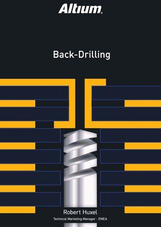
Backdrilling in Altium Designer is one of the easiest ways to improve via signal integrity. Read on to learn about back drilled vias and more.
Learn how to prevent the top 10 Design for Manufacturability (DFM) issues in your next PCB design project with these strategies. As a PCB designer, you manage a variety of different requirements and expectations.There are electrical, functional, and mechanical aspects to consider. In addition, the PCB has to be produced in a timely manner, with the best possible quality, at the lowest possible cost. And through all of these requirements, you also
One task that has always proven difficult is moving electronic product designs from one design environment to another. Whether you’ve changed design tools or acquired designs from another company, there are a number of challenges involved in moving a project from one software platform to another, while maintaining design consistency. It’s a difficult and time-consuming process, but it has to be done. INTRODUCTION If a PCB designer has a design in
Solutions for Every Role and Team
Discover and evaluate design options earlier
Develop in one shared workspace
Scale with control and compliance
Connect every stage of hardware development
Learn More