


Designing to Military Grade Electronics: PCB Specifications with Altium Designer


Military-grade PCBs carry stringent performance, sourcing, and manufacturing requirements that are encoded in a number of standards. Preparing your next printed circuit board for a military electronics system for manufacturing and assembly must also follow important sourcing and quality standards. Meeting all of these requirements is easiest when you have access to all your design and production planning tools in a single platform and Altium Designer, available within Altium Develop and Altium Agile, offers this type of design environment.
The list of standards on military PCBs is too long to list, but many of these standards are derived from the IPC-A-610E Class 3 standards. These standards specify performance requirements for high-performance electronic products that provide perpetual uptime in harsh environments. This means that military and aerospace PCBs require special consideration in terms of design, fabrication, and assembly.
In avionics, aerospace, and military systems, circuit boards are often part of a larger embedded system that almost always includes onboard processing with custom firmware, volatile and non-volatile memory, communications capabilities, and signal processing capabilities. Components in these systems must be sourced from compliant vendors in order to guarantee functionality in these systems.
Given the long list of military-grade PCB specifications, electronics designers need software that helps them comply with these standards as they create their devices. These systems carry stringent standards that are designed to guarantee performance requirements, and designers can ensure they remain compliant with these standards by working with design software built on a rules-driven design engine. Altium Designer makes this an easy task, helping you design to critical military-grade PCB specifications and verifying your layout in real time.
Key Takeaways
- Military-grade PCBs must meet extremely stringent design, performance, sourcing, and manufacturing standards (e.g., IPC Class 3, MIL-PRF specs, AS9100, ITAR) to ensure perpetual uptime in harsh environments.
- Designs must account for high current and thermal loads, EMC/ESD protection, power constraints, and reliable operation within complex embedded systems using fully compliant components.
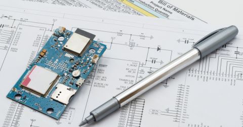
- Manufacturing and procurement are tightly controlled, limiting supplier options and requiring strict quality, traceability, and standardized documentation (BOMs, fabrication data, panelization).
- A unified, rules-driven platform can help engineers design to these standards, verify compliance in real time, and generate consistent manufacturing documentation from a single environment.
Military-Grade PCB Specifications for Design
Military-grade PCB standards are arguably the most stringent electronics standards placed on manufactured products. These systems must withstand harsh environments, tend to have higher operating requirements, and must meet a higher reliability standard in order to maintain perpetual uptime. In particular, the MIL-PRF-31032 set of standards is among the strictest that can apply to any printed circuit board. Your PCB layout, manufacturing processes, and materials are regulated under this standard. There are plenty of other aspects related to components and assembly that are specified in military standards.
Performance Requirements on Military-Grade PCBs
Military-grade PCBs should be designed to withstand maximum current and thermal loads in order to ensure reliability. These devices should also be designed to withstand and suppress ESD, meet important FCC EMC standards, and much more. Power consumption may also be an important consideration in mobile military electronic devices in order to extend battery life. Working with the right design software that includes a simulation and analysis package can help you design electronics that meet military-grade PCB specifications.
- Thermal management is one important operational aspect of military PCBs. Thermal management helps ensure your PCB remains reliable in a harsh environment.
Learn more about thermal management and dissipation techniques for your PCB.
- Aerospace and military PCBs require transient voltage protection, either implemented internally or using an external surge protector.
Learn more about ESD protection in your PCB.
- With flex and rigid-flex PCB design becoming more popular, these boards will continue making their way into military systems.
Learn more about designing your flex and rigid-flex PCB layer stackup.

Creating IPC compliant footprints in Altium Designer
Military-Grade PCB Specifications for Manufacturing
Individual PCBs for use in military and aerospace should be manufactured in conformance to MIL-PRF-50884, MIL-PRF-31032, and MIL-PRF-55110 standards. When PCBs are included as part of an embedded system, the list of specifications grows to include standards specified elsewhere in the MIL, IPC, and ISO standards. Electronic components are also regulated under ITAR and have quality requirements that are specified in the AS9100 standard for quality management.
Military-Grade PCB Standards and Manufacturing
Military quality standards on PCBs and procurement rules limit the range of acceptable manufacturers available to electronics companies and procurement officers. The manufacturer you choose should be certified to manufacture electronics for aerospace and military systems under AS9100.
Given sourcing regulations on components for military PCBs, designers and procurement officers should remain aware of quality and traceability standards for military-grade components. Whether you are producing a small PCB prototype run or are preparing for full production, your design software should help you throughout the sourcing process, ensuring you only source components from compliant distributors.
- Military PCB manufacturers need a complete bill of materials for your board in a consistent format.
Learn more about preparing bills of materials for military PCB manufacturers.
- With the defense industry being highly regulated, you need to implement procedures to help your manufacturer stay within budget and maximize yield. You can keep production costs in check by panelizing boards for your manufacturer.
Learn more about panelization and preparing panels for your PCB for your manufacturer.
- The right PCB design software package can help you quickly generate documentation directly from your design data. This helps you stay compliant and properly communicate your design intent.
Learn more about creating clear documentation for your manufacturer.

Altium's unified PCB design environment
How Does Altium Support Military PCB Design?
Altium offers electronics engineers and designers all the tools they need to take a printed circuit board from idea to production in a single environment. The design tools in Altium Designer are built on top of a single unified data model, making them easy to integrate and allowing them to access and share your design data. When your important layout, schematic design, simulation, documentation, and verification tools are accessible in a single program, you can access any feature you need without exporting data to a separate program. This streamlines your workflow and improves your productivity.
The Rules-Driven Design Engine in Altium Designer
The integrated design environment in Altium Designer is built on top of a single rules-driven design engine. This engine allows you to define design rules that govern performance and design aspects of your PCB, and your design tools can check your layout against important design rules in real time.
- The rules-driven design environment in Altium Designer helps you design to important industry and military performance standards.
Learn more about Altium Designer’s rules-driven design environment.
- With DFM being such an important aspect of military-grade PCBs, designers need design features that ease this process and help them implement DFM practices.
Learn more about maximizing yield with DFM in Altium.
- Documentation for military-grade PCB manufacturers and assembly services must be consistent and include specific information. You can easily generate this documentation for your PCB manufacturer in Altium’s unified environment.
Learn more about generating reusable batch outputs.
Altium also offers useful resources to help you get started and take your designs to the finish line. You’ll have instant access to design tutorials, the AltiumLive forum, webinars and podcasts with industry experts, and an extensive knowledge base. No other PCB design software company offers this level of support or resources for success.
No other PCB design platform can offer the adaptability and accessibility of Altium. When you work in an integrated design environment, you won’t have to switch between multiple programs and force them into a single workflow. Instead, Altium unifies important design, documentation, and component sourcing features under one roof, improving your productivity and compliance. It’s time to invest in the best circuit board design package on the market: make the switch to Altium.

关于作者
Related Technical Documentation
相关资源
目录
从设计到发布,全程无阻碍
- 让评审始终关联到正确的版本
- 减少交接中的混乱和返工
- 更早发现采购与发布风险
- 可独立工作,按需共享
开始使用
Thank you, you are now subscribed to updates.

 沪公网安备 31010502006411号