


Expert Tips for Safely Powering Up Your New PCB for the First Time

At a Glance
In this blog by expert Mark Harris, you will learn about the strategies to minimize the risk of damage to circuit boards during the initial power-up process. Read it now!


The first time you fire up on a new circuit board project can be both exciting and nerve-wracking at the same time. On the one hand, it's an opportunity to bring your creation to life. But, on the other hand, mistakes in this phase can damage the board or its components and ruin weeks or even months of work.
{"preview_thumbnail":"/sites/default/files/styles/video_embed_wysiwyg_preview/public/video_thumbnails/M1B4t4Ukrwk.jpg?itok=3yuUNYiN","video_url":"https://www.youtube.com/watch?v=M1B4t4Ukrwk","settings":{"responsive":1,"width":"854","height":"480","autoplay":1,"title_format":"@provider | @title","title_fallback":true,"loading":"lazy"},"settings_summary":["Embedded Video (Responsive, autoplaying)."]}
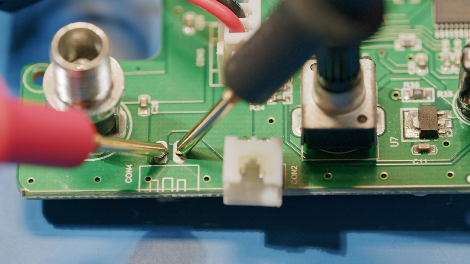
The first step in minimizing the risk of board or component damage during the initial power-up is to measure the resistance from the power rails to ground with a multimeter.
A high resistance (e.g., millions of ohms or "over-limit") indicates that there is most likely no power rail fault, while a low resistance could indicate a problem. Note that the resistance may not be in the millions of ohms if you use pull-up or pull-down resistors, or voltage dividers on the power rail.
|
High Resistance |
Low Resistance |
Once the resistance is verified, the next step is to use a current limited lab power supply to check for any problems. It is essential to set the power supply to the constant current mode, with the voltage setpoint set to the designed input for the board. If the power supply's current limit is hit, look at the power supply's voltage. If the voltage is very close to zero, the board has a short or similar fault.
Output set to 14V, Constant Current Mode Active, 4V Output, Probably a Board Fault.
Alternatively, if the voltage is near the expected value of the input voltage, the current is almost sufficient. Increasing the current limit may allow the board to operate safely.
Output voltage very close to the set point. Likely just needs a little more current.
Inrush current also needs to be considered, especially if the board has many large capacitors or powerful switching power supplies. In these cases, the inrush current can drive the power supply into the constant current mode. To avoid this problem, set the voltage to the board's typical input voltage and set the current limit about 30% higher than a rough estimate of the current draw of the circuit; remember to include LEDs! An unprogrammed microcontroller's outputs will typically be high and might turn on every LED on your board. A safe starting value is around 50-100mA, though it will depend on your schematic.
Don't miss out on the opportunity to try Altium Designer for free and see how it can help you create amazing designs! Start a free trial now.
If a defect is evident on the board, a thermal imaging camera can be an invaluable tool in identifying the problem. If a single component draws all the current on the board, it will heat up and be easily visible on the camera, even if the temperature rise is less than 1 degree. Spotting a slight temperature rise allows you to quickly identify the problematic component without delivering enough current to damage it.
A small temperature rise visible on a thermal camera.
Once the board is operating in constant voltage mode, it is vital to verify that the voltages on the power rails are producing the expected output voltages.
In summary, there are several strategies to minimize the risk of damage to circuit boards during the initial power-up process. These include using a multimeter to measure resistance, a laboratory power supply with a constant current mode, and a thermal imaging camera to identify problematic components. By following these steps, you can identify any problems with your new circuit board and put it to work safely.
关于作者
Related Technical Documentation
相关资源
从设计到发布,全程无阻碍
- 让评审始终关联到正确的版本
- 减少交接中的混乱和返工
- 更早发现采购与发布风险
- 可独立工作,按需共享
开始使用
Thank you, you are now subscribed to updates.


 沪公网安备 31010502006411号