


How to Optimize Your Power Distribution Network in Only Four Steps


Modern designers face a problem that we traditionally did not have to think about: Power Distribution Network () integrity. We have all seen the need for signal integrity for decades, but power integrity has fallen to the wayside for just as long. Traditionally we have had plenty of space to use dedicated power planes that easily supplied our designs with everything they required for operation.
But as we continue to push the physical limits of our designs, squeezing more components into smaller form factors, we need a method to optimize our Power Distribution PCB Design while maintaining shrinking form factors. What if you could optimize the shapes of your power planes directly in your design environment without ever relying on a physical prototype or simulation specialist?
PDN Analyzer™ powered by CST® provides a path to integrity within the Altium Designer® workspace. The traditionally lengthy and arduous analysis process can now be broken down into several steps that can be completed in your design environment, allowing you to make changes and re-run analysis in real time.
Here’s how you can easily optimize your in only four steps:
1. Define Your Source Power Net, Load Power Net, and Ground Net
You can find all analyzable components in your DC power rail by selecting your power, load, and ground nets. To do this, simply select the nets you want to analyze and automatically creates signal paths utilizing existing passive components to bridge the gap between nets. You never have to worry about tracing all the connections between nets.
2. Define Your Source Device and Load Device(s) Relative to One Specific DC Power Rail of Interest
All sources and loads are filtered to display only the components connected to all nets of your DC power rail. You can easily identify the important loads for your analysis with no wasted time scouring through all the components in your design looking for the right components.
3. Define Source Net Voltage and Maximum Current
Defining the voltage and current from your source is essential to determine how your will operate for analysis. In case, you can test the upper and lower limits of your design. For example, you can visually see areas of high current density and unexpected voltage drops.
Identifying these areas facilitates optimization of power shapes dimensions by showing you areas that require alteration. You also have the added benefit of determining possible resonant structures to remove from your design.
4. Define Load Net Current and Minimum Voltage Levels Relative to One Specific Power Net
You can analyze the necessary voltage and current draws from component loads to ensure their proper utilization in your Printed Boar. Visualizing the voltage and current density flows gives you peace of mind that your design will function as intended and will allow you to easily spot problems with return current in your design.
Making Analysis Accessible to Every PCB
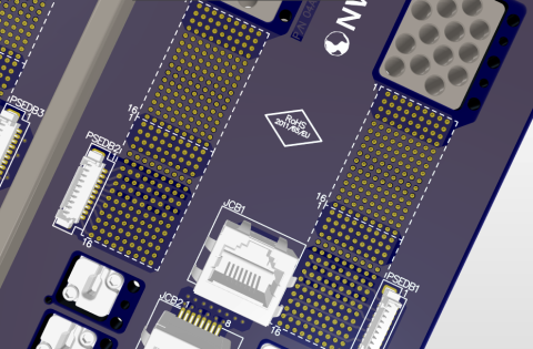
Current Density Plot from Load to Source
With these four steps, designers of every experience level can reap the benefits of analysis, including: reduced power shape dimensions, optimized return currents, and eliminated resonant ground plane shapes. Want to optimize your at design time? Register now for a free trial today
关于作者
相关资源
目录
- 1. Define Your Source Power Net, Load Power Net, and Ground Net
- 2. Define Your Source Device and Load Device(s) Relative to One Specific DC Power Rail of Interest
- 3. Define Source Net Voltage and Maximum Current
- 4. Define Load Net Current and Minimum Voltage Levels Relative to One Specific Power Net
- Making Analysis Accessible to Every PCB
从设计到发布,全程无阻碍
- 让评审始终关联到正确的版本
- 减少交接中的混乱和返工
- 更早发现采购与发布风险
- 可独立工作,按需共享
开始使用
Thank you, you are now subscribed to updates.


 沪公网安备 31010502006411号