


Structural Integrity and the Challenges of Rigid-Flex PCB Design


With the advent of rigid-flex, we’ve been able to fit more in a smaller form factor than ever before. Not only that but rigid-flex designs have an edge over rigid designs in weight and reliability. I could write a blog on just the advantages of rigid-flex, but I’ll leave that for another day. Rigid-flex is great, but there are some things you need to be aware of when you work with it. What I’d like to highlight in this blog are the routing challenges when it comes to rigid-flex design. If you’d like to learn about other challenges, I urge you to read our whitepaper on the topic.
Routing the Flex Region
When it comes to routing the flex region of your PCB design, there are some things you should keep in mind. Obviously, the main difference between routing a flex design and a rigid design is that the flexible part moves.
As an example, flexible circuits have bend requirements that fall into three main categories as defined by IPC 2223C Design Standard for Flex Printed Boards. Each of these classes has its own requirements and limitations.
- Flex to Install
- Dynamic Flex
- One Time Crease
Each of the categories has a minimum flex and rigid-flex bend specification, which is calculated as a factor of subjected copper deformity, a multiple of the finished flex thickness, and layer count.
This means there are not only electrical, but physical considerations to keep track of. You now have to worry about copper deformation as it relates to cracking and tearing, which creates more restrictions on what you can and cannot do.
For example, you can have vias but it's frowned upon to put vias in the bend region due to the stress it adds on the conductor. Not only that but you’re going to have to teardrop your vias for the same reason.
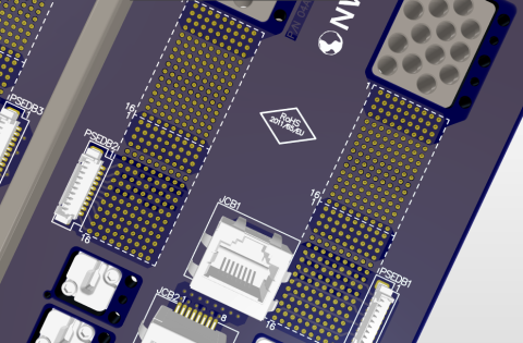
When it comes to changing widths, you must do it gradually, not abruptly. Whenever you have a track entering a pad, particularly when there is an aligned row of them as in a flex-circuit terminator (shown below), this will form a weak spot where the copper will be fatigued over time. Unless there is going to be stiffener applied or a one-time crease, it’s advisable to taper down from the pads.
Taper down traces to increase durability
When working with flex circuits you need to be thinking about stress relief to the bending areas. To help relieve pressure points it's advised to distribute your traces evenly. Also, adding wide conductors near the outside portions of your flex design will give your design more strength to ward off tearing.
Adjacent-layer copper traces (top) and staggered adjacent-layer traces (bottom)
If you need to do some double-sided flex routing, make sure to stagger your traces instead of having them lie on top of each other. This will help to relieve tension in your circuit allowing you to have a more reliable product.
The topic of rigid-flex design is a large one, and there are many things to consider, but I'd say if you have to remember one thing, that thing would be, “Bend it, don’t break it.”. This is a moving circuit, and you must now think of its structural integrity. To learn more about the challenges of creating a rigid-flex design check out this free technical white paper on surmounting the Challenges of Rigid-Flex PCB Design.
关于作者
相关资源
从设计到发布,全程无阻碍
- 让评审始终关联到正确的版本
- 减少交接中的混乱和返工
- 更早发现采购与发布风险
- 可独立工作,按需共享
开始使用
Thank you, you are now subscribed to updates.


 沪公网安备 31010502006411号