


How Are Circuit Boards Made With Altium Designer


Your printed circuit board (PCB) design might be designed to work correctly, but you also need to make sure it can actually be manufactured. Although a PCB manufacturer will fabricate and assemble your circuit boards for you, making sure your designs are manufacturable is about encoding DFM specifications in your design rules. With the rule-driven design features of Altium Designer, you can encode DFM specs into your PCB’s design rules; this means manufacturing issues will never appear again—because they will never occur in the first place!
Here’s what you need to know about defining DFMs and how are circuit boards made with Altium Designer's help.
Altium Designer is a comprehensive software package that guides you through how to make a circuit board and design successfully.
Some PCB layouts begin as a proof of concept on a breadboard and building an entirely manufacturable printed circuit board can be quite a challenge. PCB design software is what lets you place electronics components, create solder masks and choose copper foils in your circuits. Beginning with a schematic diagram, you'll need to recreate your breadboard design and transfer it to a PCB layout in order to start making functional boards.
Connecting these different parts together within the confines of the structure needs to be done while following manufacturing specification rules set by the chosen factory. Lines need to be etched using Ferric Chloride or other etching solutions; elements also require soldering without creating shorts inside this new product. With the tools available in Altium Designer, one can make sure his/her work meets all DFM demands and then move on to production successfully.
How are Circuit Boards Made and DFM Guidelines
The first step in having your PCB manufactured is a fabrication. PCB fabrication consists of making the physical PCB stack up, which comprises the core, substrate, prepreg, and surface coating or solder mask, as well as the surface trace routes and drill holes that may include vias. Defining the parameters for all of these elements is a requirement for the designer.
It is essential that the physical constraints of the fabrication and assembly equipment and processes of your PCB manufacturer be incorporated as limitations on the PCB layout design. The process of synchronizing the designed PCB structure with the one manufactured is known as DFM. Having a PCB software design package where you can see how your circuit board is made during design allows you to set DFM guidelines as design rules.
A PCB is made by etching copper pads and copper traces onto a laminated substrate. It also has another layer of foil above it to protect the bottom layers from getting etched away during production. A stencil mask, which is generated from Gerber files for your PCB layout, is used so that the manufacturing process doesn't compromise areas on your board where other components go later on. When all those steps are complete, we clean everything thoroughly - both before and after - with an acid wash just in case any residue remained (either accidentally or purposefully).
After that final step, there's one thing left to do before assembly starts: make sure your PCB will fit inside its enclosure! For smaller boards, this might seem straightforward because they're limited only by the size of their largest component. But when it comes to rigid-flex boards or ones with complex shapes then you'll need something called mechanical engineering to make sure it'll all work out when you assemble things later on.

3D views of a finished printed circuit board in Altium Designer show you what to expect from manufacturing and PCB assembly.
Incorporate DFM Rules in Your PCB Layout Tools
Enforcing DFM requirements means defining specific manufacturing tolerances in your PCB design rules before you create your layout. Some design rules that govern signal integrity and PCB assembly are specified in your high-speed signaling standards or your component datasheets. Be sure to check these resources before you start your PCB layout to ensure you can get to manufacturing without delays.
- Common design rules are intended to help ensure signal integrity and manufacturability, but you can sometimes violate these rules in specific situations.
Learn about some common design rules and when you can violate them.
- Your PCB manufacturer will run a design review on your Gerbers and other design files to catch any errors before manufacturing and PCB assembly. The right design software will help you catch any problems before you release your project for production.
Learn about common mistakes you can spot in your Gerber files.
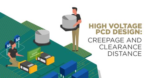
- Fitting into your enclosure and ensuring component clearances are critical parts of DFM and DFA. 3D ECAD/MCAD tools are critical here as they help prevent collisions between a circuit board, components, and enclosures.
See how you can benefit from MCAD tools in your PCB design software.
Design for Assembly (DFA) Guidelines for Your PCB Layout
The PCB assembly process is the last stage of the manufacturing process, and it is more complicated than simply attaching components. Some circuit boards are made by assembling with solder by hand, but complex devices need to be put through wave soldering to quickly assemble boards. Your board needs to be designed to accommodate the specific process that will be used to assemble your circuit board.
Another major consideration is component packaging. If you choose through-hole technology, then you may have significant fanout which reduces available space for copper traces on the surface. Conversely, if you select surface-mount technology components with pads underneath the device, you will have to include vias if you need to route traces in the inner signal layers. Your DFM and DFA requirements must work together to ensure you do not create mistakes that could delay manufacturing or cause your board to receive no-bid status.
Rules-Driven Design Software Aids DFA
Your understanding of how these and other DFA specifications affect the assembly of your board will determine the quality and reliability of your manufactured PCB. With Altium Designer, you can view the impact of your DFA specifications during design. This allows you to make any needed corrections before manufacture and avoid circuit board defects or component problems, including warpage.
- DFA is an often overlooked aspect of the manufacturing process. Your design rules can help you prevent assembly defects and ensure high board yield.
Learn why DFA is important to your PCB design and the manufacturing process.
- Problems like solder mask clearance, spacing between traces and pads, drill hits on vias, and Gerber errors can cause failed manufacturing or assembly.
- Soldering during manufacturing can also create surface-mount technology defects, but these problems can be avoided by implementing DFA guidelines in your PCB design rules.
Learn about surface-mount technology defects in PCB assembly.

Each circuit board in a multi-board system can be inspected in 3D with MCAD tools.
Prevent Manufacturing Defects with Altium Designer
Altium Designer provides multiple ways to set parameters that impact the fabrication and assembly of your circuit board. These include the PCB Rules and Constraints Editor and multiple management dialogs. The high-quality CAD tools in Altium Designer interface with your design rules to all your PCB layout parameters do not violate DFM guidelines. Everything you need to create a complete PCB design, and to prepare your design for manufacturing and PCB assembly, can be found in Altium Designer.
Altium Designer Guides You Throughout the Design Process
The entire design process is easy thanks to the schematic editor and PCB layout editor in Altium Designer. You can also view PCB layout elements while viewing your design in 3D. In addition to these capabilities, Altium Designer includes a suite of advanced functions for creating panels and manufacturing documentation for your design.
- Altium Designer’s integrated design tools include the CAD features you need to see how your PCB will be made.
See how Altium Designer’s unified PCB design environment can help you.
- If you’re still learning about PCB design and manufacturing, Altium Designer gives you the resources you need to design successfully and plan your next fabrication run.
- MCAD tools in your ECAD software will help you spot problems in your finished product. You’ll have access to these features and many more in Altium Designer.
Use Altium Designer 3D View to simply integrate ECAD and MCAD.

3D view of your panelized PCBs before manufacturing
The success of how PCB designs are made and development depends on coordination with your PCB manufacturer to ensure you follow their DFM guidelines on copper placement, routing traces, solder defects, and much more. With Altium Designer, you can see a realistic view of your circuit board during design and define your application requirements in your design rules.
Altium Designer on Altium 365 delivers an unprecedented amount of integration to the electronics industry until now relegated to the world of software development, allowing designers to work from home and reach unprecedented levels of efficiency.
We have only scratched the surface of what is possible to do with Altium Designer on Altium 365. You can check the product page for a more in-depth feature description or one of the On-Demand Webinars.

关于作者
Related Technical Documentation
相关资源
目录
从设计到发布,全程无阻碍
- 让评审始终关联到正确的版本
- 减少交接中的混乱和返工
- 更早发现采购与发布风险
- 可独立工作,按需共享
开始使用
Thank you, you are now subscribed to updates.


 沪公网安备 31010502006411号