Serial Communications Protocols - Introduction


In this series of articles, we will be looking at some of the different types of Serial Communication Protocols available to transfer information between microcontrollers, data-producing and data-processing peripherals, and other smart devices. The articles that follow this introduction to serial communications will cover some of the more popular protocols in common usage. At the end of this series, we will summarize the advantages and disadvantages of each. We hope this resource will prove valuable next time you find yourself needing to implement a serial communication bus, helping you choose the best option for your particular circumstances.
These days digital electronics have become the most significant part of most electronic devices on the market. Many different chips are in use where their complex operations are dependent on information sent to and from other similar digital components. Common protocol standards have been created to enable communication between these. Imagine if each IC or device communicated using its unique protocol. This would be the same as if every human talked using their unique language. It would be chaos because it would be near impossible for any of us to understand each other.
We currently have different memory ICs, digital sensors, protection devices, programmable power supplies, digital potentiometers, radio frequency ICs, etc. All need to communicate between each other or with microcontrollers, microprocessors, FPGA, or ASIC. The purpose of these communications between devices can vary greatly. It can be for programming to extract information, providing a signal to initiate an action’s performance.
Also, some protocols give us humans the ability to interact with the ICs through microcontrollers. You can send a signal to a microcontroller that is programmed to send a signal to an IC through one of these protocols. Alternatively, you can connect one of the debug available tools.
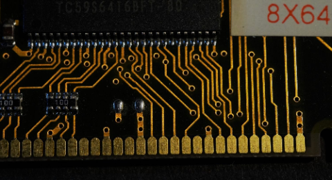
One of the problems with serial communications is the difficulty of finding and debugging your circuit if something goes wrong. Suppose data is not getting from one device to another. In that case, the fault may exist in one or more of the following places: in the logic of the transmitting device, in its circuit design, in how it’s encoded the serial communications, in the communications bus, in the decoding by the receiver, in the circuit design of the receiver or finally in the logic of the receiver. Sticking an oscilloscope probe on the serial communications may allow you to see if there is any activity but will tell you little of its validity. To fully see what’s going on, you’ll need either an oscilloscope with a decoding function or a logic analyzer. This will allow you to know the voltage pulses traveling across the pulse to fault find voltage levels, spot any noise issues, and look for problems with the signal rise and fall rates.
However, to thoroughly debug the serial communications, you’ll need a tool that can decode the data on the bus to see if it’s correct or if it’s been corrupted or affected by collisions. A considerable number of debug tools have been created specifically to debug communications between devices or ICs. One of the industry-standard logic analyzers is the Saleae Logic series of logic analyzers, with the Pro model offering sufficient speed to analyze all the most popular protocols.
Many lower-cost logic analyzers are too slow to handle higher-speed protocols such as SPI. The LA2016 Logic Analyser offers sample rates between the Saleae Logic 8 and Logic 8 Pro for a very low cost; I own one and have used it very successfully to analyze protocols.
Also, the consideration of communication protocols is crucial for both firmware and hardware design. From the hardware side, you should always carefully go through your chosen microcontroller’s datasheet. MCUs can only communicate with predefined protocols using dedicated pins. The designer will need to decide what ICs will be used and what protocols they will require in advance of selecting their MCU.
For example, the STMicroelectronics STM32F103C8T6 device fitted to the popular STM32 Blue Pill development board includes 2 x I2C, 3 x USART, 2 x SPI, and 1 x CAN communication interfaces. However, some of the pins for these communications protocols are shared. For example, if we look at pin 14 of the device, which is labeled PA4. This pin has both USART and SPI functions. This means that you can’t use all the listed SPI and USART interfaces for your design simultaneously. You need to choose which ones you need when and plan accordingly or search for another microcontroller that supports more communications interfaces. Of course, the PA4 pin can be used for both communications protocols by changing its configuration in operation. However, you still need to carefully consider at what times it will be used to function because they can’t be used simultaneously. This will increase both the hardware and firmware design complexity.

Serial communication pins in microcontrollers can overlap, so read datasheets carefullyYou need to download and use the appropriate IC communication library module based on what protocols the device will use from communications from the firmware side.
Although there are many communication protocols, the most popular ones are SPI and I2C. Each of the protocols has its applications, communication speeds, design considerations, advantages, and disadvantages. We will go through each of them in turn in this series of articles.
Summary
In the next article of this series we will be looking at the popular UART device and discuss some of their advantages and implementation details. We will end the series by comparing the different protocols, highlighting their key advantages and disadvantages.
Have more questions? Call an expert at Altium and discover how we can help you with your next PCB design.
关于作者
Related Technical Documentation

相关资源


目录
Get the Full Signal Analyzer Experience
- Turn SI analysis into fast, coordinated decisions.
- Your Agile Teams evaluation includes full access to Signal Analyzer.
Contact Us
Thank you, you are now subscribed to updates.
 沪公网安备 31010502006411号