


SMA Edge Connector Transitions in an RF PCB

At a Glance
SMA edge connector footprints sometimes require ground clearance below the connector’s coaxial pin. We’ll show why this can arise and how to qualify the need for ground clearance.


In my recent power amplifier module project, I showed the high-level view of how to place and route various components in a power module that used some basic components. In the module, SMA edge connectors were used to bring in power and bring out the generated RF signal at 6.3 GHz. But there was one thing I forgot to include in one of my SMA connector footprints: ground clearance below one of the solder pads in the SMA footprint.
I’m a bit embarrassed because the system that formed the basis of this example project did include the ground clearance. In some RF designs, it is important to include the correct ground clearance below certain components as part of impedance matching, much in the same way you might increase the ground clearance around an impedance matching network.
In this article, I’ll show why the need for larger ground clearance below an SMA edge connector can arise, as well as evaluate the need for additional clearance in the PCB. I’ll also show some simulation results that illustrate the effects of ground clearance below the connector’s signal pin.
What Can Happen On Large SMA Connector Landing Pads
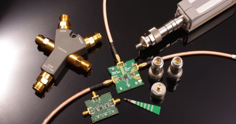
When the landing pad on an SMA edge connector footprint is very large, it can create a potential for an impedance mismatch. When you look at an SMA edge connector like the Taoglas EMPCB.SMAFSTJ.B.HT, it’s easy to see that the pin on the back side of the connector is quite large. This requires a wider and longer landing pad so that the connector can be soldered onto the edge of the PCB.
Take a look at the example below, where an input 50 Ohm feedline is connected to an SMA edge connector in the power module project. If you look at the pad as if it was just a short transmission line, you would find that its characteristic impedance is about 14 Ohms.

Although the pad is short, this is enough to create a significant deviation in the target 50 Ohm input impedance looking into the SMA edge connector. It’s appropriate to ask whether this will create excessive reflections, which can be evaluated by looking at an S11 plot.
When dealing with this problem, we have three possible options for ensuring closer impedance matching:
- Remove some ground below the pad so that input impedance deviation is minimal
- Place a taper between the transmission line and the pad
- Both #1 and #2
By first removing some of the ground around the landing pad, it’s possible to increase the input impedance looking into the pad so that it is much closer to 50 Ohms.
Alternative Design
An alternative design that implements both techniques is shown below. Two changes were applied: placing a ground cutout below the pad on L2 and L3, and adding a taper in addition to the ground cutout (Option #3)

What happens when ground is cleared on L2 and L3? We will still have ground on L4 and L1, so L4 will be the bottom reference for the pad. This basically means we have an alternative coplanar waveguide configuration; we just need to adjust the pad-to-pour spacing on L1 to hit the target impedance of 50 Ohms.
As we can see from the Impedance results in the Layer Stack Manager, we find that the 50 Ohm target is hit for our 50 mil wide pad by simply increasing the coplanar ground clearance from 6 mil to 10 mil.

In the next section, we want to look at the S11 curve for this interconnect with no ground clearance, with the clearance only (Option #1), and with the clearance + taper arrangement shown above (Option #3).
S11 Results
The image below shows simulated S11 curves for three arrangements (no clearance/taper, clearance applied, and clearance + taper). These curves were simulated individually in Simbeor and then compiled into Excel. The dashed line shows the target operating frequency of 6.3 GHz. Note that the connector body was not part of the simulation; a much more accurate simulation would require including the connector body and performing a 3D field solver simulation with it, or including the connector body as part of the linear network for this system.

The results above show that the GND clearance arrangement with no taper offers the best performance at the target frequency, although the design with the taper would still be acceptable. The design with the taper can be improved as a rigorous taper design process was not implemented in this simple example. Try adjusting the taper length and profile for yourself and see if you get better results; you can also follow the linked guide below.
Other SMA Connectors Might Work Better
There are other SMA connectors that may not require the same kind of ground clearance below the signal pin like we have in the case of the edge connector shown above. These other SMA connectors, such as the Amphenol 901-10511-1 shown below, use a much smaller signal pin, and this pin would require a smaller landing pad to ensure a large enough solder fillet.

Because this component uses a much smaller signal pin at the center of the connector body, it does not require a large landing pad and it is much easier to match the pin to a thin trace. This means there will naturally be a much closer match between the pad’s input impedance looking into the PCB side and the transmission line’s characteristic impedance. Because of this closer match, you may only need to remove a small amount of coplanar ground. It’s also much easier to just size the transmission line exactly to the pad, so no additional matching solutions are needed.
Anytime you need to place connectors and ground clearances in your PCB layout, use the complete set of PCB design and production tools in Altium Designer®. Once you’ve finished your PCB layout and you’re ready to share your manufacturing deliverables, you can easily share data and release files to your team with the Altium 365™ platform.
We have only scratched the surface of what’s possible with Altium Designer on Altium 365. Start your free trial of Altium Designer + Altium 365 today.

关于作者
Related Technical Documentation
相关资源
目录
从设计到发布,全程无阻碍
- 让评审始终关联到正确的版本
- 减少交接中的混乱和返工
- 更早发现采购与发布风险
- 可独立工作,按需共享
开始使用
Thank you, you are now subscribed to updates.


 沪公网安备 31010502006411号