


Types of PTFE Materials for RF PCB Design

At a Glance
PTFE (Teflon) PCB materials are sometimes seen as the magic bullet for your RF PCB stackups. Make sure you choose the right type of PTFE-based material for your design.


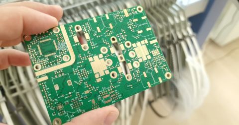
RF PCB designs often make use of low-loss PTFE-based materials thanks to their very low dielectric losses and huge range of possible Dk values. These materials use polytetrafluoroethylene (PTFE) as the base material, but this is not the only constituent in these laminate materials. There are also reinforcements and fillers that are used to engineer PTFE PCB materials to have their required material properties.
Commercially available PTFE-based materials are available with or without reinforcement, but it is the designer’s job to specify what they need to ensure reliability and functionality. Before you run off selecting just any PTFE-based material for your board, make sure you understand how fillers and reinforcements in PTFE laminates affect your board’s operation.
Material Components in PTFE Laminates
PTFE-based materials include two main material components that define their material properties:
- Reinforcement - provides rigidity
- Filler - ceramic powders used to engineer the material properties
PTFE laminates used in PCBs use ceramic particles as a filler material to engineer the material properties of the laminate material. The exact effects on material properties depend on the type of ceramic used and its content in the substrate, and this is largely the intellectual property of PTFE laminate manufacturers.
In addition to the use of ceramic fillers to engineer thermal, mechanical, and electromagnetic properties, PTFE-based laminates can include a reinforcement in the PTFE matrix.
Glass Weave Reinforced
Glass reinforcements are a standard reinforcement used in PTFE-based materials for RF PCBs. These reinforcements are the same woven glass fabric styles that are found in standard epoxy-fiberglass laminates. Due to the lower rigidity of PTFE laminate materials compared to FR4, reinforcement can increase the overall rigidity of the board if that is required to ensure reliability. It also simplifies drilling throughout a stackup, including in hybrid stackups.
The typical glass styles used for reinforcement include:
- 1078
- 106
- 1080
- Spread/flat glass
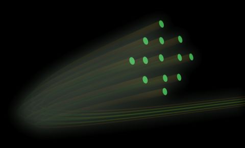
How do these weave styles differ, and how do they create differences in phase response across circuits? In general, more open weaves will create greater deviation between your target phase response on an interconnect, and the actual (measured) phase response, which is the classic fiber weave effect. This is bad for any phase-sensitive system, such as phased arrays.

If you need to design and manufacture a system with a target phase response with minimal skew, then you should use spread/flat glass reinforcement, or no reinforcement at all. There are also non-woven glass and ceramic reinforcements.
Non-Woven Glass Reinforced
There is also a type of glass reinforcement that is completely random. In this PTFE-based material, you can typically find the same level of mechanical rigidity you would find in woven-reinforced laminates, but without the same level of fiber weave effects you would see in a woven-reinforced laminate. The use of non-woven glasses in PTFE laminates is much less common because not all manufacturers offer this option in their materials. However, if it is offered (see below), the material properties in woven vs. non-woven reinforced PTFE are similar.

Ceramic Reinforced vs. Ceramic Filled
The use of glass reinforcements has allowed the use of thinner PTFE-based materials in PCB stackups, which requires rigidity be enforced in the PTFE matrix. However, glass is not the only available reinforcement; ceramic reinforcements are also used to provide rigidity. These reinforcements also provide the same function as fillers, but they do not provide the same kind of mechanical reinforcement as glass weaves.
I bring up ceramic as a reinforcement because these materials are sometimes called out specifically as ceramic reinforcements, not just ceramic fill. Ceramic reinforcement does not contain a weave style, and so you do not have fiber weave effects in the PCB laminate. However, the line between ceramic reinforcement and ceramic filling is blurry and some vendors may use these two terms interchangeably. Be careful to check whether there is a meaningful difference before finalizing a material selection.
Unreinforced
Finally, there are unreinforced PTFE laminates, which only contain a ceramic microparticle filler and additives, but no other reinforcements. Many of the PTFE-based laminate products you will find available are available in reinforced or unreinforced varieties. I think most designers assume that their PTFE laminate will be unreinforced, but unless you specify exactly what you need you will be at the mercy of your fabrication house’s material stocks.
Advantages: Why would we use an unreinforced material? We would do this if we want to eliminate any possibility of the reinforcement creating fiber weave or skew effects along interconnects in the substrate material. This is the main advantage of these materials, especially for use in very high frequency systems like radar. There are also benefits in high-density advanced radars that might use blind vias on outer buildup layers, namely:
- Skew elimination across phase-matched RF lines
- Elimination of knuckle areas where fiber strands overlap

Disadvantages: The main disadvantage of an unreinforced PTFE-based material is its lack of rigidity before it is applied into a stackup and cured. This can result in layer-to-layer misregistration, particularly in drill holes and pads, which could have some slight misalignment. On the modern boards I mentioned above, this can be a significant source of return loss at very high frequencies.
I don’t want to say that these materials will always have greater misregistration, but it is possible for them to have greater misregistration if your fabrication house is not experienced working with these materials. I have heard an application engineer from Rogers describe these unreinforced laminates as “wet noodles”, meaning they are very limp and can flex when being added to the stackup. If you are going to use unreinforced, make sure your fabricator is experienced in handling these materials.
Whenever you need to design an RF PCB with any type of PTFE-based PCB laminate material, use the complete set of PCB design features and world-class CAD tools in Altium Designer®. To implement collaboration in today’s cross-disciplinary environment, innovative companies are using the Altium 365™ platform to easily share design data and put projects into manufacturing.
We have only scratched the surface of what’s possible with Altium Designer on Altium 365. Start your free trial of Altium Designer + Altium 365 today.

关于作者
Related Technical Documentation
相关资源
目录
从设计到发布,全程无阻碍
- 让评审始终关联到正确的版本
- 减少交接中的混乱和返工
- 更早发现采购与发布风险
- 可独立工作,按需共享
开始使用
Thank you, you are now subscribed to updates.


 沪公网安备 31010502006411号