


Advantages of Flexible Circuits for Space Applications

At a Glance
Flexible circuits reduce weight in spacecraft and can be used in enclosures where there is minimal available space.


To the outside observer, it might seem that flex and rigid-flex PCBs originated in devices with movable parts, such as mobile phones and laptops, with the idea of eliminating or consolidating cables. The truth is that they trace their origins back to military and aerospace systems in the 1960s. There were several motivations for developing these types of PCBs and assemblies, and the benefits found in aerospace systems can also be enjoyed in other systems.
Flex PCBs Are Lightweight and Low Volume
In aerospace systems, particularly in launch vehicles that will bring a payload into orbit, anything that can be done to reduce weight is top of mind by systems designers. Back in my classical mechanics class in grad school, we were once given a homework problem looking at the amount of fuel required to bring a payload into low-earth orbit for a given thrust value. On an order of magnitude basis, one finds that the majority of the weight of a launch vehicle would need to be allocated to fuel simply to put the craft into low earth orbit. By reducing the overall weight of the craft, less fuel would be required to travel a given distance.
This brings us to the biggest benefit of flex PCBs for use in space: reduced weight. A flex circuit tends to have lower mass than the same board on a rigid substrate. For a single PCB, the difference may be minor, but if you add up the weight for all the boards in a spacecraft, the weight difference can be significant.
Flex PCBs can also take up less space than rigid PCBs making them perfect for aerospace. Obviously, a thin film takes up less space than a thick rigid substrate, but the main volume savings come from flexibility. Whereas a traditional board needs a set amount of 3D space, a flexible PCB can be squeezed or folded into an enclosure. They can be bent into unique 3D shapes and fill unused space.
Some of the other major advantages are summarized in the table below.
|
|
|
|
|
|
|
|
|
|
|
|
Kapton®
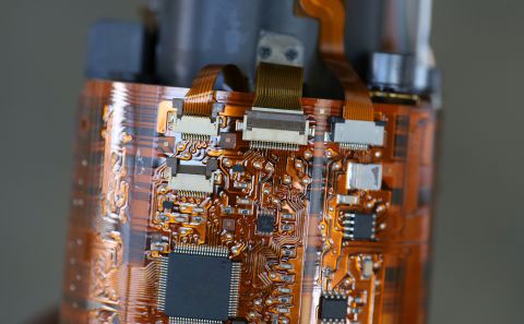
There is a small collection of materials that are used in standard flexible circuits. The primary material used in these PCBs is polyimide, sometimes known by its brand name of Kapton®. This thin polyimide film that has already been used on multiple space missions for everything from heaters to solar cells.
The polyimide layer used in flex PCBs is often identified as a flex ribbon cable between two rigid board sections (i.e., rigid-flex). However, it can be used in any number of applications within an assembly. Polyimide can be used as a connector, cable replacement, as the main substrate for components and circuits, or all of these simultaneously.
Assembly Tips For Further Weight Reduction
To get all the weight and size reduction benefits of a flex PCB, let's look at some of the standard uses of flex PCBs in a larger assembly or product. For space applications, the goals in these designs are to reduce weight through reduced component count, consolidation of components, or replacement of components with a flex PCB section. Some strategies for flex PCB usage in these ways include:
- Replacement of cables or wires with a flex ribbon
- Replacement of a multiboard assembly with a single flex/rigid-flex PCB
- Consolidation of components and interconnects into a single rigid-flex assembly
To learn more about these design strategies for flexible circuits, take a look at our guidebook on rigid-flex design and manuafcturing.
When you need PCB design software that enables design of flex PCBs and rigid-flex PCBs, use the complete set of CAD features in Altium Designer® to build your most advanced products. When you’ve finished your design, and you want to release files to your manufacturer, the Altium 365™ platform makes it easy to collaborate and share your projects.
We have only scratched the surface of what’s possible with Altium Designer on Altium 365. Start your free trial of Altium Designer + Altium 365 today.

关于作者
Related Technical Documentation
相关资源
从设计到发布,全程无阻碍
- 让评审始终关联到正确的版本
- 减少交接中的混乱和返工
- 更早发现采购与发布风险
- 可独立工作,按需共享
开始使用
Thank you, you are now subscribed to updates.


 沪公网安备 31010502006411号